Chapter 8
Headrest, Heat Duct, Seat Belt
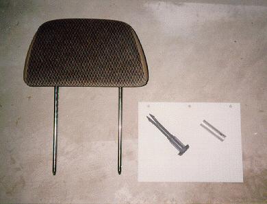
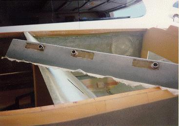
I don't like the headrests that the plans call for because they are very... "triangular"! In a plane like this with all the nice smooth curves, it just didn't look right to me. I decided to do an installation of my own which involved adding automotive type headrests. Specifically the head rests I will use are similar to those from my '96 Dodge Caravan. Very light, rounded and already covered in upholstery. They slide up and down in plastic sleeves that I had to purchase from the dealer (for about $3 each, 2 required for each headrest) and can be removed. This will come in handy when passengers are climbing into the rear seats. The sleeves are held firm by a piece of aluminum tubing permanently bonded to the shoulder support. Here are the pieces of the headrest.
First I fabricated the shoulder support and made longer plywood shoulder belt attach points. The longer length will allow me to install the aluminum tube which holds the sleeve in place for the headrest. I then glassed the inside of the foam.
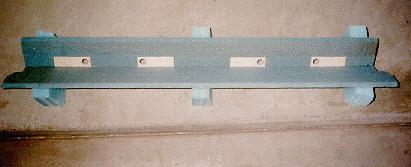
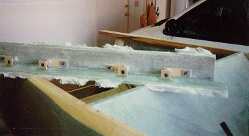
After glassing the inside surface I added another support for the bottom of the tube and glassed it in place. I flipped the piece over and installed hard points for the shoulder belt attachments. After cure I fabricated some shims and attached nutplates to them for the shoulder belt bolts. Here are some of the details.
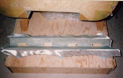
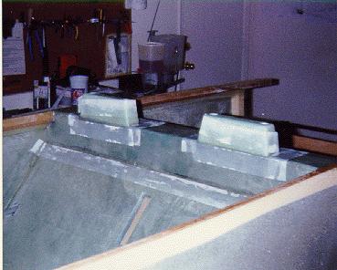
The shoulder piece was then installed on the fuselage seatback and glassed in place. I added a couple of risers for the head rests so that the sleeves would be flush and contoured them to an appealing shape. I glassed them and once cured I flox'd them to the shoulder support fairing them in with micro and tape. Here is a pictures of the shoulder support risers during cure.
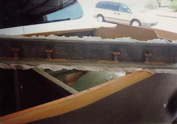
In order to make slightly more room for the rear seat passengers, I decided to make a bench seat in the rear instead of the two individual seats the plans call for. This seemed easy enough, but I had to re-design the rear center duct so that it wouldn't interfere with the seat. I ran the duct to the thigh support bulkhead which I ran in one piece across the fuselage. The duct runs from the front seat back support and has two channels in it for control cables & wiring as well as heat. The heat will be vented out from under the seat and I plan to put a heater source under the seat instead of using ducting from the engine exhaust. The control cables (throttle, mixture, etc.) will be routed to the sides of the fuselage and then into the engine compartment. Here are a couple of photos of the duct and bulkhead.
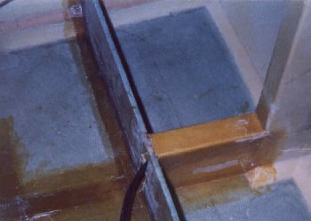
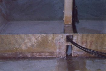
I then fabricated the rear seat back support and thigh support and mounted them with hinges to the floor. The center duct in the plans was the location for the seat belt attachment so again I had to design something different. I made a small triangle of foam 1-1/2 inches wide and attached a tube across the top for the seat belt attach bolt to go through. I then micro'd this to the floor and applied 9 layers of UNI across the top just as if it were done on top of the duct. I then crossed this with a few layers of BID alternating fore and aft and crossways. After cure I opened up the glass so that the tubes were open again. Here is the seat belt attach point.
I finished the chapter by installing the outer seat belt attach brackets. These are essentially angle brackets mounted on a 1/4 inch birch plywood reinforcement pad which has been covered with 7 layers of BID overlapping onto the fuselage at the specified locations. Two 1/4 inch bolts holes are then drilled and counter bored from the outside of the fuselage for attaching each bracket. The bolt heads are then potted in flox and blended in with the outer contours of the fuselage. This is done for three of the brackets. The final bracket is identical in shape but the bolts holes are drilled and countersunk through the entry step which mounts permanently on the outside of the fuselage on the pilots side. Here four bolts are used - two to mount the bracket and two to secure the outer edges of the step. I'll wait until I finish contour the fuselage before mounting this last bracket and step.