Chapter 13
Part 1:Nose Gear
The nose gear chapter includes building the retractable nose gear, forming and glassing the nose of the fuselage and installing the rudder pedals and brake cylinders. I purchased several prefabricated pieces from two vendors - Ken Brock Manufacturing and Featherlite. Brock's supplied all the metal components such as the retract mechanism, spring strut, strut pivot, brackets, nose wheel fork assembly and crank. Featherlite supplied the nose cone, wheel well, strut cover, NG-30 cover and nose gear strut. I started building the NG-30's which are the primary structural support of the nose and nose gear. It houses the nose gear retract mechanism and the nose gear strut and is mounted to the front of the fuselage (directly to F-22 bulkhead).
The NG-30's are glassed on both sides and match drilled for the retract mechanism and strut pivot as well as having additional structural members added at critical locations. The NG-30's, strut pivot, and the retract mechanism are assembled together and attached to F-22. Prior to fitting it to the fuselage I fabricated and attached the F-0 bulkhead to the assembly by laying it flat on the table and setting the assembly on top of it, attaching it with flox and BID tape. Marc Zeitlin had done it this way on his project and noted that it worked well and seemed simpler than the way the plans had you do it. The plans say to add the bulkhead after the assembly is attached to the fuselage. I liked Marc's idea and it worked fine.
I then began working on the gear strut by cutting it to length. It had to be ground down in a couple of spots as well so that the fork assembly and pivot would fit correctly. I then wrapped it with BID per plans and let it cure. I assembled the strut to the NG-30's and tested the mechanism for smoothness.
After mounting the gear, I then attached the assembly to the front of the fuselage. Here you can see the assembly process.
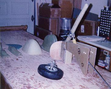

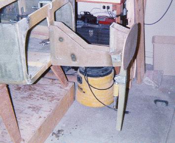
After completing the installation of the nose gear retract crank mechanism, I decided I didn't like the mechanical system and purchased an electric nose lift device from Steven Wright. His unit required slight modification to the F-22 bulkhead. After making the mod's and installing the electric system, I am much more pleased with the robustness of the nose gear. I also now have the ability to lift the nose electrically with passengers in the aircraft without straining by back to crank it down! In case of electrical failure I still have the ability to hand crank the motor gearing as well. Here are a few pictures of the installation.
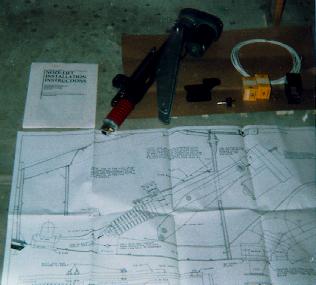
New Jack Wilhelmson nose gear motor and automatic extension unit - updated June 7, 2005
After my gear up landing incident, I had to install a new nose gear strut. While taking apart the old hardware (NG15, NG3, NG4, foot, etc.) from the old strut I realized the steel parts were showing signs of rust even though they had been painted black prior to attaching them. The strut was built probably 7 or 8 years ago, so I was concerned about reusing them. I looked at Jack Wilhelmson's web site - he makes a lightweight electric nose gear system similar to the one I had purchased from Steve Write. Jack sells the NG3 and foot parts made of stainless steel and I decided to order these to prevent the corrosion from reoccurring. Jack also sells a new tapered roller bearing NG6 that is superior to the stock Brock part and should eliminate any wear of the nose gear hinge as is found on many EZ's. Since I had to rebuild the strut anyway, now would be a good time to replace my stock NG6 as well (even though I haven't noticed any wear yet). Well, this whole project came about because I forgot to lower the nose and it sure would be nice to have an automatic system to lower the nose if I should ever forget in the future. Wouldn't you know, Jack sells one of those too! OK, I should have stopped right there and said good enough, but Jack's gear extension motor is much lighter and compact than my Wright systems. I would be nice to get rid of a few pounds in the plane instead of always adding...but my system has worked fine and never given me a problem...But I'll have the plane apart anyway - why not just retrofit the whole system and take advantage of the pre-wired harness that Jack has for his system. I vacillated like this for a couple of days before finally deciding to give Jack a call. He had just returned from Sun and Fun but was willing to answer all my questions about the gear motor and auto retract system. I decided to order the whole package and sent him a check that afternoon. Jack told me I'd have to wait a week or so before my order would be ready to ship, so realizing it would be two weeks before I'd be working on the plane again, I decided to finish my backyard BBQ awning and paint the kitchen for my wife!
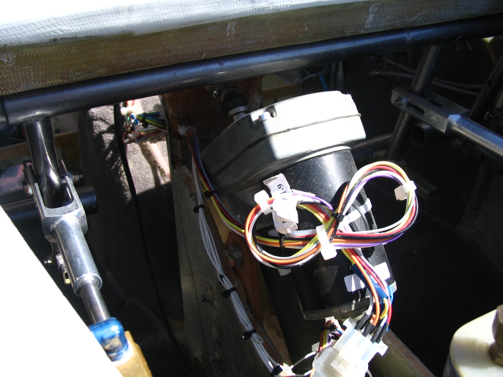
The box from Jack arrived on Monday, May 9th. I went to the airport and pulled the old gear motor and wiring from the plane the week before, so it would be ready to drop the new system in. OK, not quite drop in. I fit the new NG3 to my strut to make sure it fit, then floxed my NG15 nose wheel hardware onto the strut after ensuring I wouldn't need to do any more glass work to it. The new gear motor mounts are much smaller that my old ones, but do require a couple of holes to be drilled. The holes are supposed to match up to 3 holes already reinforced for the mechanical nose hardware. Well, Jack should include a drawing of where those holes are supposed to go for anyone not using a mechanical system to begin with. The plans drawings show where two of the holes go and the third is located by using the mechanical hardware as a template! Oh well, I figured out where a good place for it to be was and drilled out the holes. The motor mounts forward of F22 whereas my old system actually had to have part of F22 removed to allow the motor to stick thru it. But it had the advantage of not sticking up above the NG30's. Jacks motor does and so I'll have to make some new covers for the strut to keep the air leaks to a minimum.
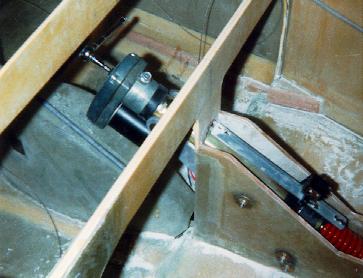
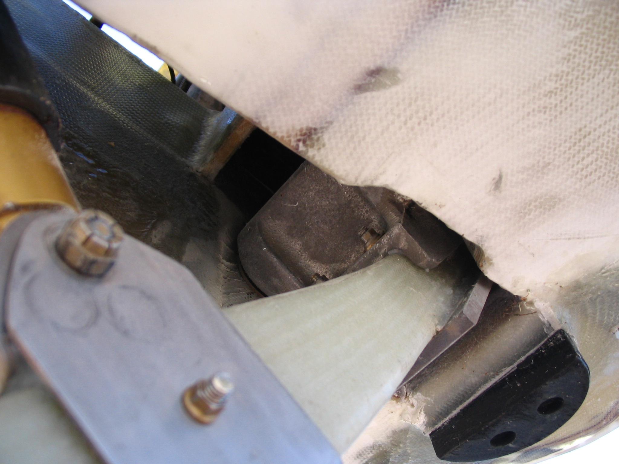
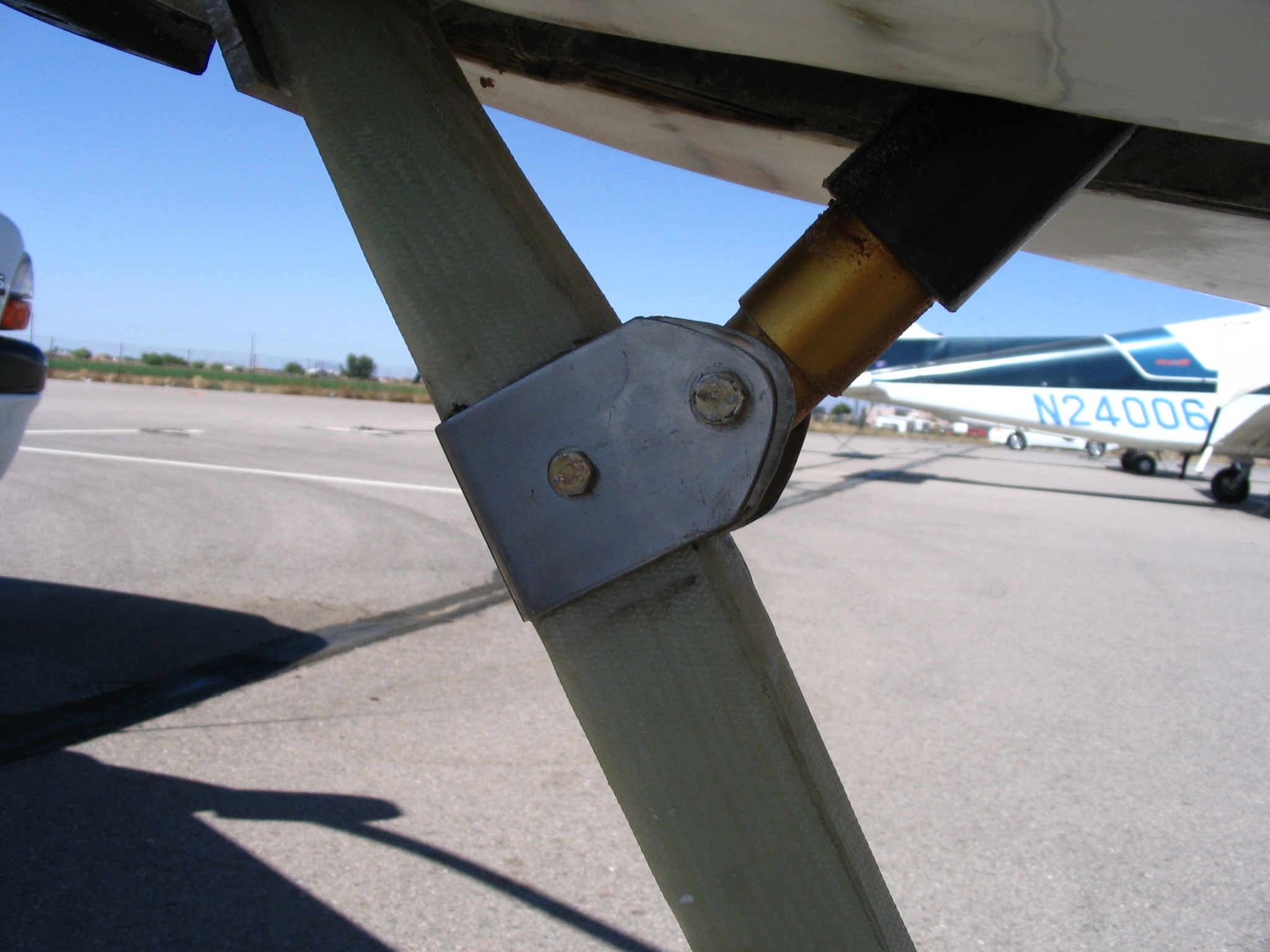
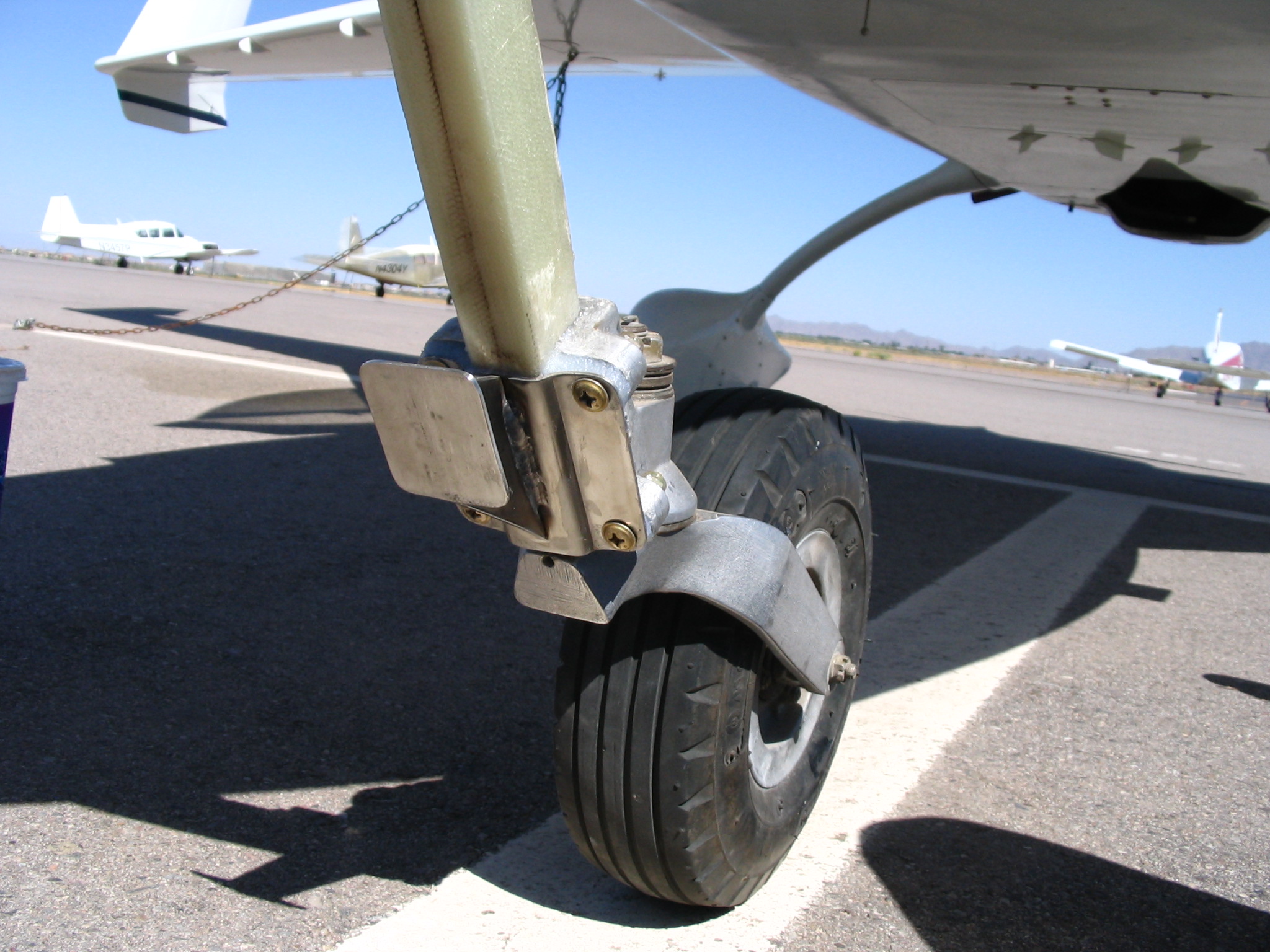
Installing the motor is a breeze one the hardware is secured. I test fit the strut and new NG3 to make sure I had good clearance and that it hung straight. Once satisfied, I drilled the holes thru the strut and attached the NG3 and NG2 plate with flox and bolted them together with the plans hardware. My new electric generator sure comes in handy at the airport now that I am without a hangar. I pull my truck up to the plane, start up the generator in the truck bed and can use all my electric appliances as required. This saves me having to take the parts home to drill. After it cured, I removed the strut and made the new strut covers. I did this a little different from the plans but the result is the same. The idea is just to keep air from coming into the plane as much as possible when the gear is down. There is a hole in the cover to allow the motor extension to attach to the strut, but that's it. Once the gear is up the gear doors close off any further air. Here are some pictures of the new hardware. The first is the new NG6 tucked up inside the front of the NG30. You can see some of the contour filler on the nose from it's repair. The next two pictures show the stainless NG3 and NG4 attached to the new gear actuator strut and the new stainless "foot" used to take stress off the nose fork during extension and retraction.
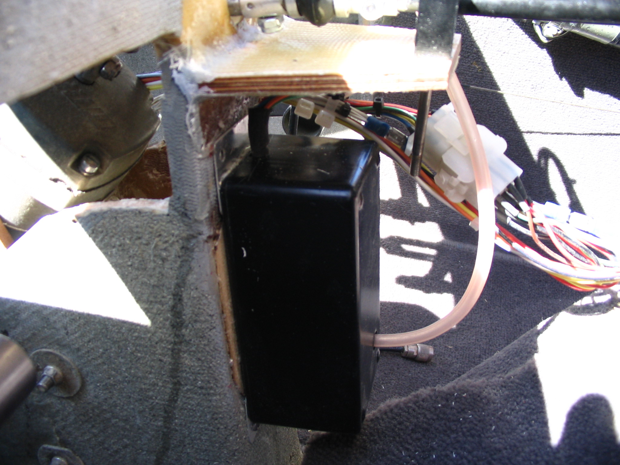
Here are a few pictures of the motor and AEX installation. The first is the new gear motor and wiring harness. The second picture is the automatic extension unit (AEX). The pink colored hose coming out of the unit is ties into the pitot system to measure airspeed. The unit is programmed to drop the gear no matter what the switch setting once the airspeed gets below about 90 knots. I mounted the AEX to the aft side of F22.
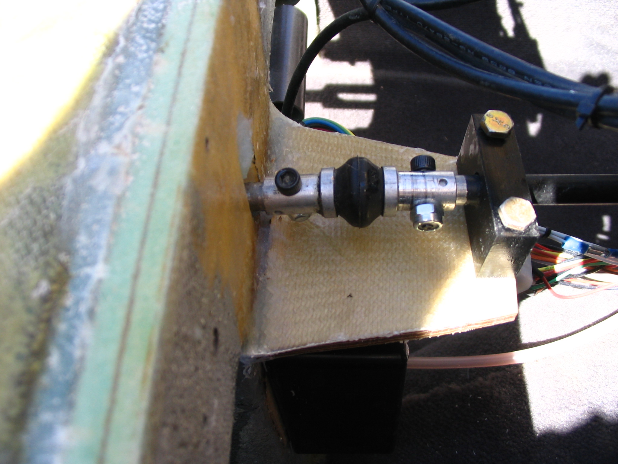
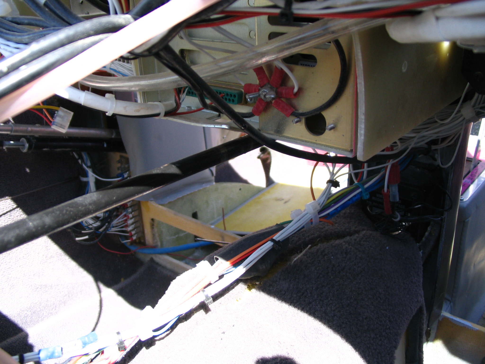
One of the features I never installed with my last nose gear was a mechanical override that would allow me to lower or raise the gear in the event of a electrical or motor failure. Jack provides the necessary hardware to do this so I definitely decided that I was going to install it this time. The standard system is a rod attached to the motor that exits at the instrument panel and allows a socket wrench to be used to crank the gear. The rod has a single u-joint in it allowing the rod to exit near the top of the instrument panel. I had to add an additional U-joint in the system to allow the rod to exit at the bottom of the panel because I have too many radios in the way to use the standard setup. The rod exits next to the gear switch. Here are some pictures to explain. The first is a shot of the second u-joint. It is attached just aft of F22 about 3 inches behind the first u-joint mounted on the motor. This second u-joint needs to be supported so I built a wood brace floxed to F22. The wood is covered with two plies each side of BID and overlaps F22 as well. I then made a Delrin bushing block and bolted it to the brace. The shaft goes through the Delrin bushing and protrudes through the lower instrument panel through a rubber grommet just below my MX20. The second picture shows the shaft as it just clears the bottom of the MX20.
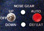
The electrical hookups were straightforward, but as is my habit I traced the physical wires and matched them to the schematic to ensure they were correct as well as to get a basic understanding of the system. Sure enough, one of the connectors that Jack supplied had a wire in the wrong position. After calling him to verify the harness was wrong and not the schematic, I fixed the connector. I had to attach a dozen or so wires to the connector once I determine my specific wire lengths but that was easy enough. Jack supplies a nice little switch panel with two LEDs and two switches. The picture below shows the switch panel. The gear manual extension rod is shown to the right and above the switch panel. It protrudes about two inches from the panel and is made to accept a 1/4" drive ratchet handle. I keep this in my map compartment on the front seat back.
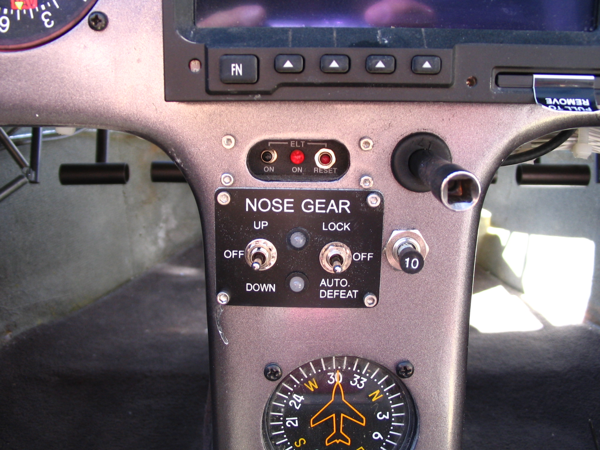
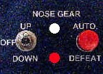
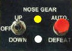
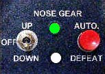
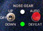
The switch on the left is the gear up/down switch. The switch on the right is a manual override as well as a lock switch. With this switch locked, the automatic extension system is "hot". Moving this to off allows the gear to be lowered mechanically without having a load on the motor. The system automatically retracts the gear when airspeed exceeds 90 knots or lowers the gear if airspeed falls below 90 knots. The auto-defeat is used to override the automatic extension system for 20 seconds. The two LEDs are status indicators for the gear. These images/depictions were taken directly from Jacks site.
|
|
| RUNNING UP | UP |
|
|
| RUNNING DOWN | DOWN |
 |
|
| OFF |
I have a 10A circuit breaker to the right of the switch panel which is somewhat different than what Jack recommends on his schematic. Normally as soon as I turn on the master, the AEX will notice the plane isn't going faster than 90 knots and extend the gear. It's a good safety feature to ensure the motor and AEX are functional prior to flight, but can be an annoyance. My installation allows me the option to pull the breaker if I want to power up the panel without the gear extending so I get the best of both worlds.