Chapter 13
Part 3:Rudder Pedals
For all that they are, the plans rudder pedals are sure an expensive item! I looked into designing a set myself that would be adjustable and also incorporate toe brakes, but decided in the end to stick with the plans - sort of. The plans call for a left and right set with only the right side adjustable. The pilot side had some additional weldments on it for the plans version of the brake cylinder actuators. I liked the idea of adjustable pedals on both sides, so I order two sets of right side pedals. This meant turning the pilot's side set around so that they connected to the other pair correctly. A couple of small tabs were all that were facing backwards (one for a return spring and the other for connecting the rudder cable), but this setup still works fine.
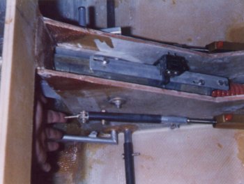
The pedals are fitted with tubes connected between them and running through NG-31. I flox'd two sets of brass bushings into NG-31 so the pedals rotated smoothly and bolted everything together. The left rudder cable connects to a tab on the pilots left pedal and the right cable connects to a tab on the co-pilot right pedal. Here is a picture of the pedals.
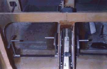
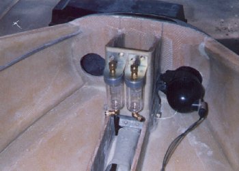
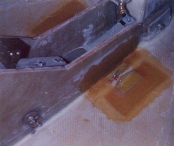
The rudder pedals double as brake pedals in this design. The brake master cylinders are attached to the floor of the nose by a couple of angle brackets I glassed in. The brake fluid reservoirs are located on NG-30 near the nose cone. As the rudders are fully deflected the brakes become actuated by the pedal pushing on the brake master cylinder. The travel of the pedal prior to braking is taken up by a sliding tube connected to the master cylinder. Here are some pictures of the detail.
Velocity Rudder Pedals - Updated 6/17/2005
So after installing the plans version of the pedals I decided after flying off my 40 hours to make some changes. I installed a set of standard Velocity rudder pedals in the nose and remounted the brake master cylinders as well. The plans pedals always appeared flimsy to me and for what they cost I could have done the Velocity pedals cheaper from the beginning. I highly recommend the Velocity pedals as a retrofit.
The new pedals hang from the F22 canard brace instead of being floor mounted. They hang from two aluminum bushing blocks that are mounted to the brace with two AN3 bolts each. I put mine as far forward as I could on the brace to give me maximum legroom. The foot pedals are adjustable in and out and will accommodate a 3 inch length adjustment.
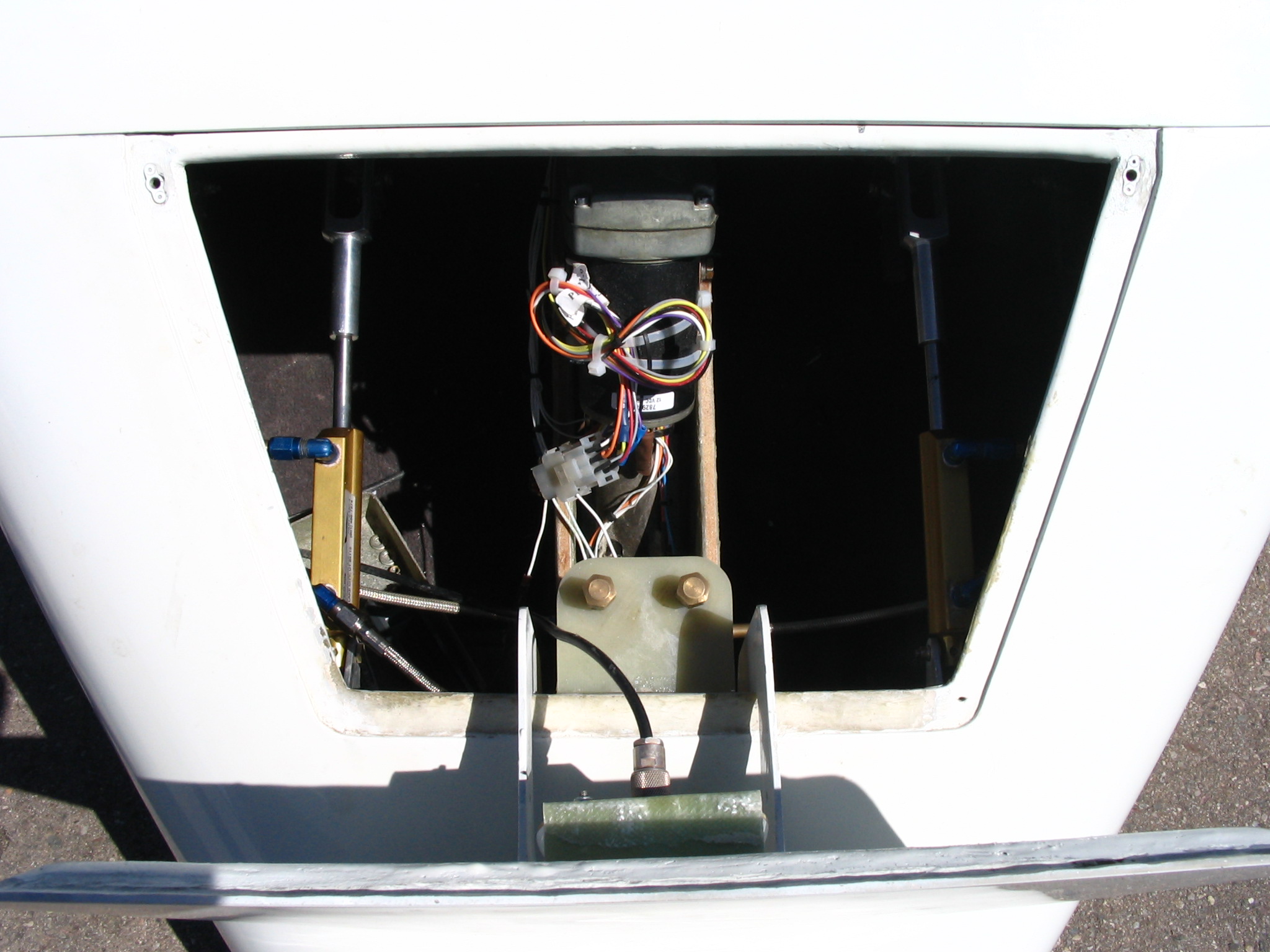
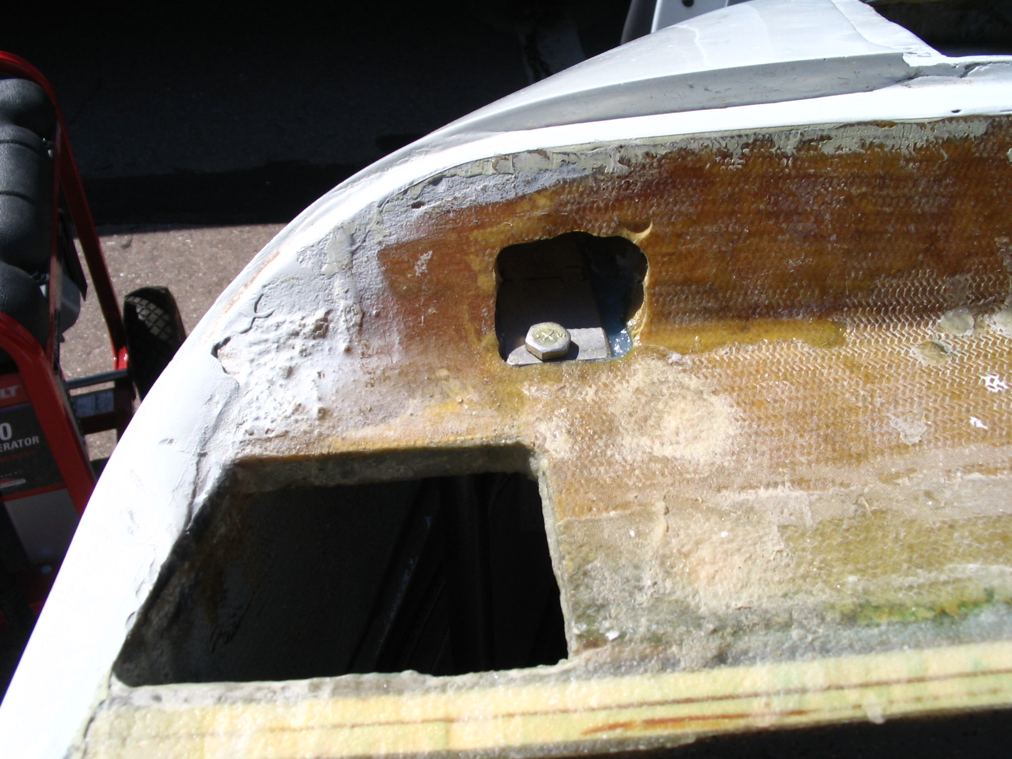
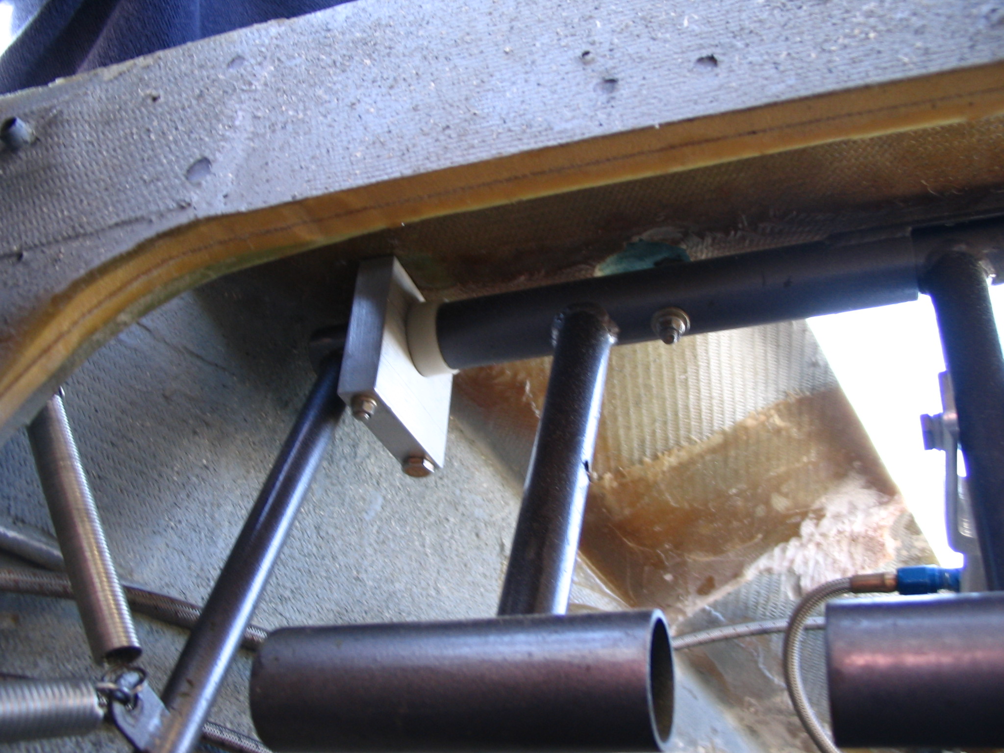
Here are some pictures of the installation. The first picture is the hole I burrowed out in the canard brace/nose top. You can make out the head of one of the AN3 bolts in the picture. I removed foam locally and filled this area in with flox and mounted a metal plate to act as a hardstop for the bolts. The bolt in the picture is able to be installed with the threads down and the second bolt (back in the black hole out of site) is actually inserted from the bottom and a nut is installed from within the pocket. I slight bit cumbersome, but you shouldn't have to remove them often. The second picture is shown from the pilot's side and shows the aluminum bushing block from underneath. You can sort of make out how the bolts go in opposite directions from this picture. The pedals are seen to the right of the bushing block with the large foot pegs at the bottom of the picture. These are adjusted in and out by removing a bolt and sliding them to a new position. I have mine adjusted all the way in. as I have longer legs than most. The tube running parallel to the rudders and to the left of the bushing block is the rudder cable arm. A tab is welded to the end of this rod for attaching the rudder cable. Mine have two springs attached with the upper spring being a return spring to bring the pedals back to the neutral position after actuation. The lower spring also attaches to the tab with the other end of the spring attached to the rudder cable. Since I have internal rudder bellhorns, once the rudder travel is reached the spring allows the brakes to be actuated without putting more tension on the rudder cable.
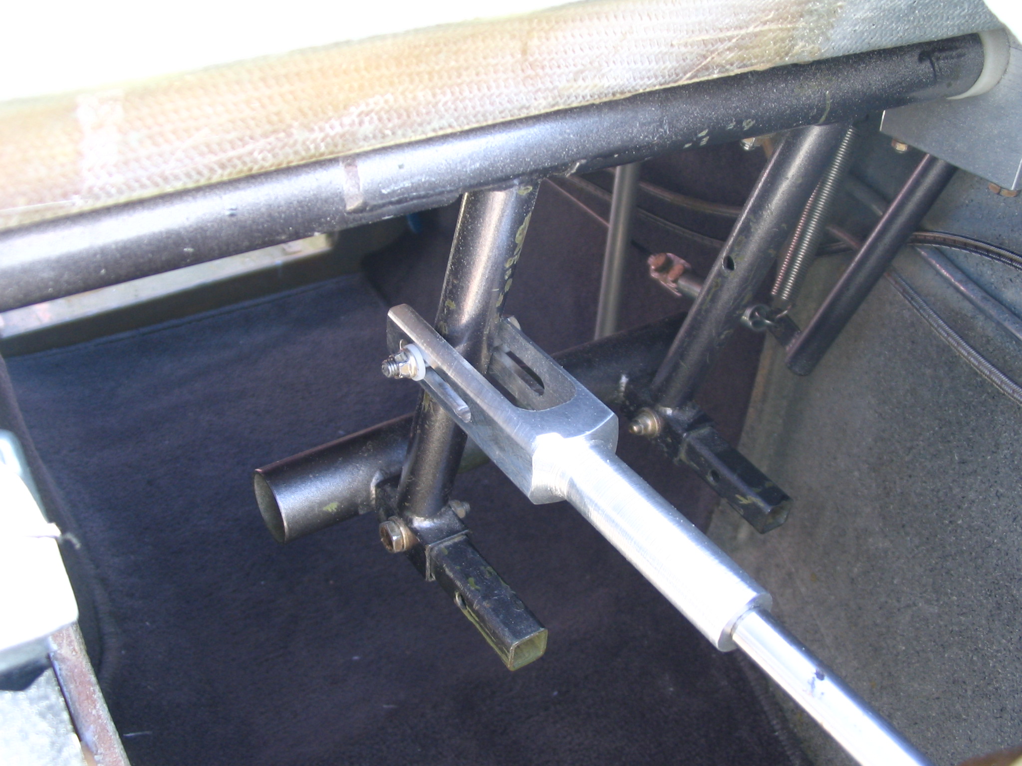
The next picture show the pilot side rudder pedals as viewed through the nose top. The right rudder pedal (the one on the left in this picture) is connected to the brake master cylinder actuator. This is a piece of aluminum I designed after seeing a similar piece on Steve Wrights StaggerEZ. A fellow Cozy builder, Dale Rogers, made these up for me on his lathe and mill. The actuator is threaded onto the end of the Matco laydown master cylinder and has a slot wide enough for the rudder pedal to slide within. A bolt is inserted thru the actuator and thru a hole in the rudder pedal. As the pedal is compressed the bolt slides in a slot until it reaches the end of the slot. Once the bolt hits the end of the slot the master cylinder is then actuated by further pushing on the rudder pedal. The slot is designed to allow the rudders to be fully deflected at the end of the slot. The adjustable foot pegs can be seen in this view as well. The picture to the right is the Matco brake master cylinder on the co-pilots side. It is attached in the same manner as the one on the pilot side but to the left rudder pedal. This cylinder actuates the left brake. The brake line at the rear of the master cylinder (the one on the left in the picture) is routed to the parking brake and from there to the left rear wheel. A couple of aluminum brackets are embedded in flox and support the master cylinder. You can make out one of the brackets just below the brake line. The brake line at the front of the master cylinder goes to the fluid reservoir which is mounted on NG30. You can see the filler caps in the lower left of the picture.
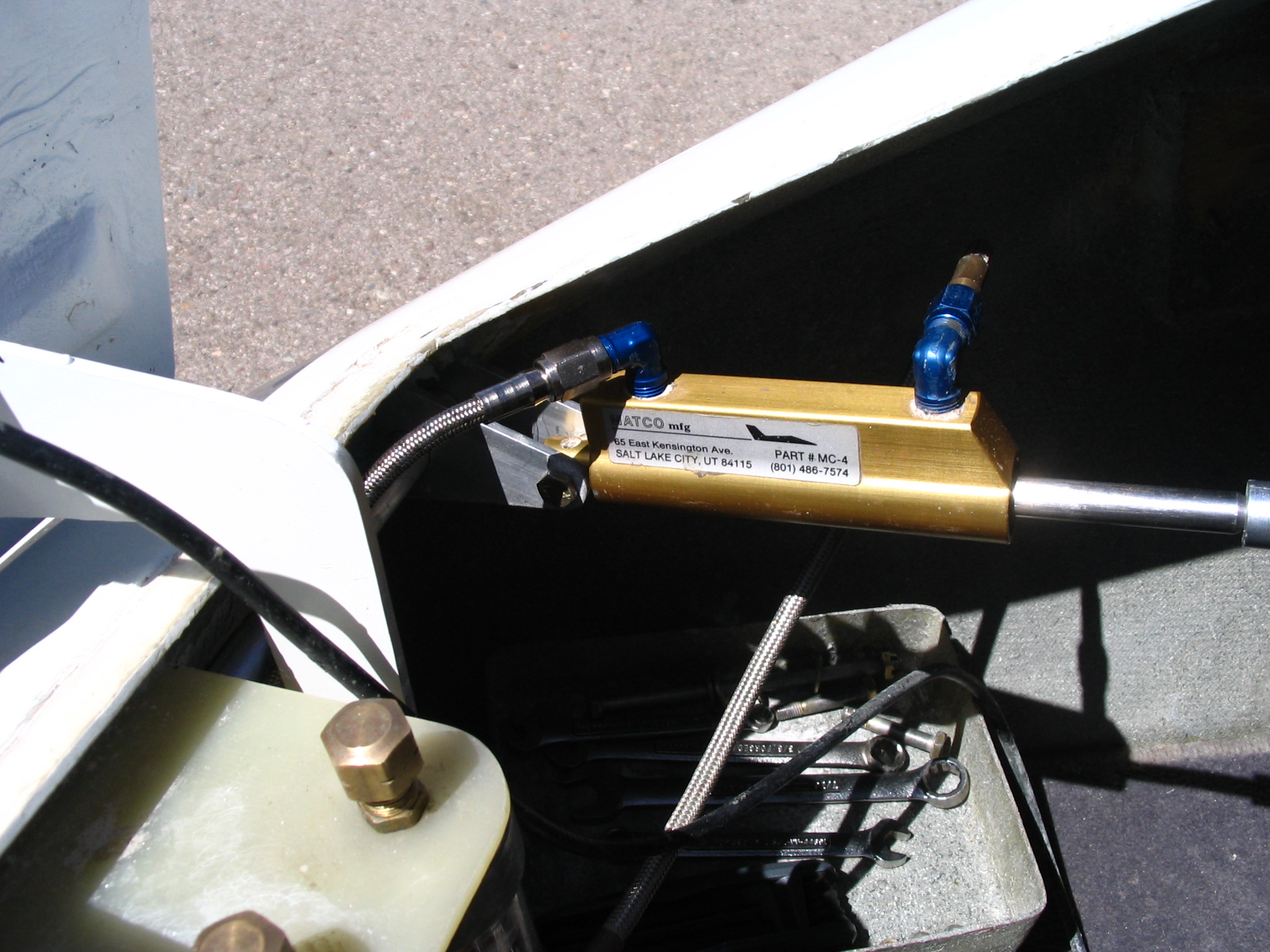
This last picture shows the setup as viewed looking down through the nose access door.