Chapter 14
Centersection Spar
After completing the nose section, I am ready to fabricate the center section main wing spar. This is a long (over 11 feet) hollow beam shape that will become a permanent part of the fuselage. The outer wing sections will bolt onto this spar. I will be adding some additional material to the ends of the spar so that I can mount a retractable landing gear in the future. The additional material is essentially a crush plate made up of 15 plies of BID as well as layers of UNI for the load on the gear. I will point out where the modifications are as I do them.
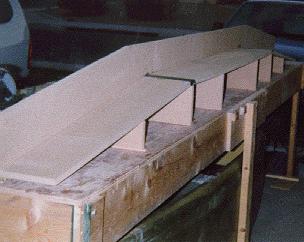
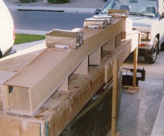
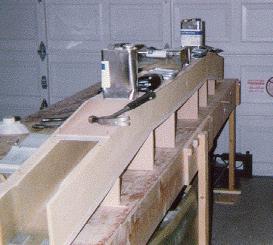
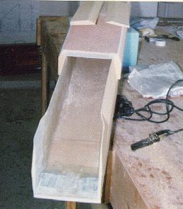
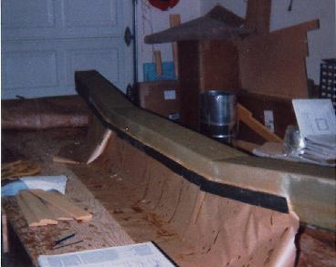
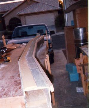
In preparation for the fabrication of the spar, a jig is built to hold all the foam pieces square and ensure a perfectly shaped spar. The jig is made of 3/4" particle board that is Bondo'd to my table top. After the jig is built, the foam pieces are cut and bonded together. The top, aft and bottom sides of the spar are assembled in the jig with the aft face laying flat. This forms a "C" channel with the top and bottom sides sticking up from the jig and laying on the aft face. I then cut all the metal wing attach plates to size per the plans and cleaned them up with 220 grit sandpaper. After I micro'd the foam together and let it cure I was ready for the first glass lay-up which covers the interior of the spar. Here are some shots of the spar jig and the foam being glued together. Note I used the forward face foam pieces to hold everything square as it cured (as laid in the jig, these pieces are on top).
The plans say to do this interior lay-up in one step with no cure in between steps. I had heard that this step could take up to eight hours, but I didn't have a whole day to dedicate to the lay-up. What I did instead is work on the right half of the spar in one night and the left half on another night. This worked out great since it cut the lay-up schedule in half. The only place where there was a joint was in the middle of the spar and it was a single layer of BID. The real intent of not letting the lay-up cure is that there are multiple layers in critical areas of the spar where hard points are added. These hard points later hold the wing attach bolt bushings.
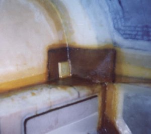
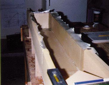
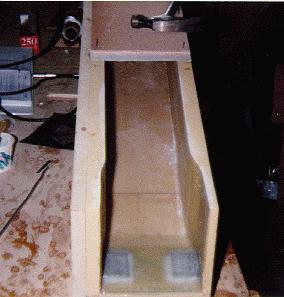
Anyway, the interior gets a single ply of BID all over, then a bulkhead is placed at B.L. 35. This bulkhead gets a BID layer on each face overlapping the spar sides to the appropriate length. I did not install the spar end bulkheads at this time because I will be installing the retractable landing gear and the bulkhead will need to be removed for easy access to the trunion. After the gear is installed, I will install the bulkhead. A reinforcing lay-up of three plies UNI at B.L 33 is then laid up over the top and aft interior face. Then I flox'd a single LWA1 plate on the aft interior face centered at B.L. 33 and snug against the top interior face. I flox'd the edges for a smooth transition and covered the LWA1 with one ply of BID overlapping an inch all around. I then moved to the end of the spar and laid up a single 5 inch wide layer of BID across all three faces followed by three layers of UNI 4 inches wide and of the appropriate length. This was all centered at B.L. 65.5. I then flox'd two LWA1 plates on the aft interior face centered at B.L. 65.5. One was snug against the top interior face and the other snug against the bottom interior face. Again, I flox'd the edges and laid up a single ply of BID overlapping both LWA1's by an inch all around. After this cured I repeated the whole thing for the left side of the spar, overlapping the center joint one inch after roughing the surface of the cured glass from the right side lay-up. The center bulkhead was then micro'd in place and a single layer of BID was laid up on each face overlapping the spar faces. Here are some photos of the interior lay-up with bulkheads in place as well as some of the LWA1's.
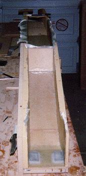
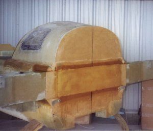
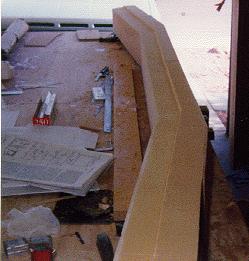
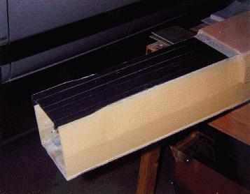
The foam for the forward face of the spar was glassed next. Here is where I modified the steps slightly to allow for the retractable gear installation. I cut the foam to the length called for in the plans but then cut 19 inches off of that length at each end, saving the cutoff. I laid the cutoff pieces on the spar and traced a line from the inside where it met the top and bottom pieces of the spar. I then cut the foam along these lines so that the foam would fit inside the spar instead of on top. Going back to the other pieces, I laid the foam out with the inside surface up and glassed with 1 ply BID. At the ends where the 19 inches were cut off, I extended the glass an additional 1-1/2 inches by butting a scrap piece of foam to the end and covering it with peal ply prior to laying on the glass. After it cured, I pulled the scrap piece off leaving a nice overlap. I then micro'd the pieces to the spar to complete the box. The cutoffs fit up underneath the overlaps I created and act as support for the crush plate reinforcing lay-ups. They will be covered with duct tape first so the lay-up will not stick to the foam. Here are photos of the sequence just described. You can see the scrap foam for the overlap in the first photo as well as the detail of the final work in the last photo.
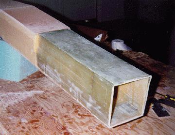
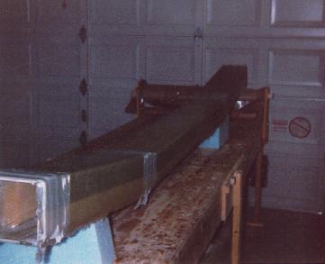
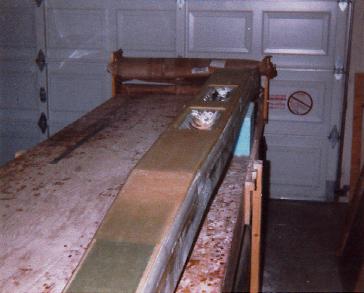
The spar is then removed from the jig and spar cap troughs are cut at the top and bottom to the correct depth. Then some foam from the aft face is removed locally to allow additional LWA plates to be installed flush with the surface with flox. The forward face is then beveled on the top and bottom edges full span. Here are a couple of pictures showing the spar troughs and LWA plates.
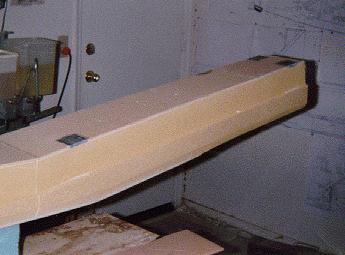
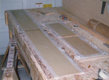
This is where I took a detour from the plans and installed the retractable landing gear reinforcement lay-ups and crush plates. The crush plates are made up of 15 plies of BID, but I decided to use a 0.200 inch thick plate of G-10 instead. A local machine shop gave me a sheet 20x12 inches which I cut to two pieces of 19x5.4 inches roughed up on each face to allow for better adhesion. I then cut off the top and bottom foam at an angle from a point 19 inches inboard from each end of the spar and put them aside for reattachment later. The cut is angled from the bottom of the spar trough to the front inner face of the spar. I then duct taped the cutoffs of the forward face foam and temporarily installed them to act as support for the reinforcing lay-up until it cured. The reinforcing lay-up is a 19 inch long, multi-ply lay-up of UNI cloth at 30 degree orientation which is laid up on the table and wet out. I placed the wetted lay-up on the end of the spar centered on the forward face inserts I made from the cutoffs and overlapping the top and bottom sides of the spar extending over the lip I created to the end of the spar (19 inches total). I then placed the crush plate in place directly over this reinforcing lay-up on the forward face and peal ply'd all exposed glass surfaces. After a complete cure, I sanded any rough edges. Here is a series of photos showing the end of the spar after removing the foam, with the duct taped support in place, during reinforcement lay-up/crush plate cure and finally the end product.
After all that I got back on track with the plans and prepared the aft face for the shear web lay-up. I jigged the spar with the aft side up and taped off exposed foam. The shear web is four plies of UNI alternating at 45 degrees full span. The lay-up extends from the inside edge of the top spar cap trough, over the aft face and then to the inside edge of the bottom spar cap trough. This entire lay-up was peel ply'd since it will get additional lay-ups in the future. Here is the spar ready for the shear web lay-up. You can see some foam that was removed from each end of the spar for adding the landing gear reinforcement. These were added back on after the shear web was cured and prior to spar cap lay-ups.
After that cured, I removed the peel ply and sanded the spar trough areas thoroughly in preparation for the spar cap lay-ups. I re installed the foam that was removed locally for the landing gear reinforcement and built a dam of 1X2 boards on the back side of the spar to complete the "trough". The spar cap is laid up using the same technique as the canard. The trough is wetted out full span and multiple layers of the 3 inch wide tape are laid down in the trough. The bottom spar cap is made up of 17 layers with the first 7 layers extending full span. The remaining layers get smaller until the last layer is approximately 44 inches long (verses 135 inches full span) all of which are centered at mid span. I started the lay-up at 7pm on Monday night and finished at 1am Tuesday morning - a long haul. Here is the spar with the dams prior to filling in the spar cap.
After that lay-up cured, I trimmed the spar cap ends and flipped the spar over to do the top spar cap lay-up. This lay-up has 23 layers since it will be in compression (Fiberglass is much stronger in tension (the lower spar cap is in tension) and therefore requires more layers when in compression). Anyway, I prepared the spar with the dams and taped everything off and cut the spar cap cloth to the appropriate lengths a day before doing the actual lay-up. This saved a tremendous amount of time when it came to doing the actual lay-up. I completed the lay-up of the top spar cap in 4-1/2 hours averaging 5 layers per hour. After it cured I trimmed the ends and took the spar outdoors to do some sanding. Here's a plug for Arizona weather - December 15th was a clear and warm 75 degrees. Sorry to you folks in the northeast who are shivering! The spar had accumulated a lot of epoxy drips and runs between the dams and the shear web and the spar caps aft edges needed to be rounded for the next lay-up. Sanding all this off took the better part of three hours because I really didn't have the proper sander to do it quick. After cleaning up all the dust the spar was nice and smooth and ready for the next lay-up.
Christmas week of 1996 I glassed the final 4 plies of UNI over the aft side and extending down both the top and bottom sides full span. I then flox'd the outer LWA plates in position and flox'd a bead around the edges for a smooth transition for additional plies of UNI over the LWA's as well as a final BID layer to cap it off. I then went to New Jersey for the holidays. Here is the spar at this stage with the peel ply over the LWA's.
Access holes were then cut in the front face and I proceeded to glass the final 2 full span plies of UNI across the front of the spar. This lay-up extends over the top and bottom sides a couple of inches. The access area received some glass to glass treatment as well. The front face comes in contact with fuel since part of it is a wall of the fuel tank in the strake. This got a generous coating of epoxy to ensure there will be no leaking. This is a photo of the spar after glassing. You can see the access hole locations with dry glass in them prior top trimming it out.
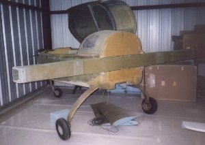
I stopped work in this chapter until I could move into a hangar and permanently attach the spar. In February of 1999, I was finally in a hangar and able to get back to mounting the spar in the fuselage. I started by leveling the fuselage fore and aft and side to side. Then I test fit the spar into the fuselage and leveled it along with making sure it was square with the fuselage. After ensuring all of that, I pulled the spar out of the fuselage and prepared to drill the wing attach holes.
I took the center spar and laid out the dimensions called for to drill the pilot holes for the wing bolt bushings. After drilling them through with the 1/4 inch holes, I leveled the spar and lined up each wing along the floor of the hangar. I fitted the left wing to the spar being careful to line up everything level, then clamped it in place. Then I did the same with the right wing. I used a combination of a laser pointer, water level and carpenter's level to get it all right. After making minor adjustments for about an hour and deciding that everything lined up good and straight, I drilled the pilot holes through the wing hardpoints.
I then opened up each of the hardpoint holes to 5/8 inch using the spot face going nice and slow to keep the heat from building up. It took about 90 minutes to do both wings. I will mount the bushings in the holes after building the strakes.
I then applied flox to the spar cutout in the fuselage and placed the spar back in. I adjusted it for level and squareness again and then allowed it to cure. I then BID taped the joints both inside and out as in the plans and let that cure. The final steps here involved floxing two small plywood firewall pieces to the rear of the spar as well as a piece of 1/4 inch foam between them. The plywood pieces were fabricated along with the firewall and have three screws permanently attached to each of them for mounting rudder pulley brackets. The foam is then covered with a ply of BID extending out onto the firewall and inch in each direction. That completes chapter 14! Here are some photos of the spar mounting steps.