Chapter 19
Wings and Ailerons
I decided to purchase a set of pre-molded wing spars and pre-cut foam cores for the main wings to help speed along the building process a little. They were purchased from AeroCad and will require a slight variation in the plan's method of building the wings. The main difference is that I won't need to build the elaborate jigs to hold everything together and it should cut a considerable number of hours off the construction time.
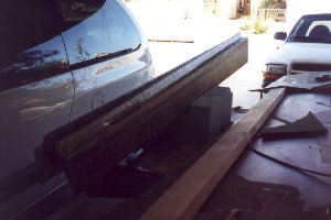
I received the spars and pre-cut wing cores along with the main gear legs in the same shipment (see chapter 9) and decided to complete the gear installation first before moving on to the wings. So, I stored the spars and cores at my in-law's home until I can make room to construct them. Here is a picture of the pre-molded spars as I received them from AeroCad.
After getting a storage building to store the fuselage, I had room in my garage to start work on the wings. I sanded the main spars with 50 grit to roughen the surface for a good bond of the foam cores. I leveled each spar and bonded the leading edge cores in place, making sure the level lines on the cores were perpendicular to the spar face. The next day I was able to flip the spars over and install the trailing edge cores in a similar manner. I decided to skin one wing at a time, choosing the left wing as the first (for no particular reason).
The bottom of the wing gets glassed first, so I 5-minute glued an aluminum I-beam to the trailing edge of the TOP side of the wing with about 1 inch of the beam off the edge. It is on this edge that the glass will be extended making a flat and very straight trailing edge. I installed a backup NAV antenna (similar to the one in the fuselage belly) just forward of the spar cap on the inboard side of the wing and routed the coax through the pre-cut wire chase in the cores. I will install a marker beacon antenna in the other wing.
After filling in small dings and low spots with dry micro, I checked the inboard and outboard level lines to make sure they were level with each other. I then wet out the wing with wet micro and laid up 2 plies of UNI glass crossing each other as explained in the plans. A piece of BID was installed at the wing tip as well as a couple of small sections of UNI near the inboard attach areas. At knife trim stage, I trimmed the glass along the leading edge as well as the trailing edge and filled the trailing edge recess with dry micro to bring it into contour with the wing surface. I also peal ply'd the leading edge along with some other areas as specified in the plans. After a two day cure, I popped the I-beam off the wing (taking some good sized chunks of foam with it) and turned it over to prepare the top side for glassing.
I had a small setback at this point! - I separated my right collarbone (while mowing my grass of all things) and that pretty much took care of spreading epoxy around on a wing for about two weeks! I had my arm in a sling until the 17th of October and felt good enough to start preparing the top surface a day or so later. I also discovered at this point that someone had helped themselves to my camera (read stolen) that I use to help document my work and put on these WEB pages! So, I'm missing a few pictures of the left wing, but I'll make it up when I get started on the right wing. That explains the lack of pictures in this chapter so far!
Susan and I flipped the wing over so that the top surface was up and I routed out a groove for the rudder conduit. I placed the conduit into the groove and held it in place about every 6 inches with toothpicks. I then filled the groove with dry micro, essentially potting the conduit in place. After allowing it to cure, I sanded the wing surface smooth and filled in low spots with dry micro. Most of the micro was along the edge of the spar and at the trailing edge where the I-beam had torn loose the foam when I removed it. When I was satisfied with the surface, I glassed the upper skin using the lay-up schedule called out in the plans and allowed it to cure for a couple of days.
I then carved out the inboard rib areas, contoured them to the shape required for the future addition of the control hardware and glassed them in. I also laid up a couple of UNI layers across the inboard and outboard wing attach hardpoints and cut the access hole for the outboard wing attach.
At this point I decided to repeat the whole process again on the right wing. After both sides were glassed and cured I laid out the measurements for the ailerons and cut them out. I used a straight edge to keep the cut as straight as possible and this worked out very well. I was VERY disappointed in the quality of the pre-cut ailerons however! After removing the ailerons and setting them on my worktable, I started to test fit the metal inserts that get bonded to the ailerons and realized the cores were cut at some angle approximately 15-20 degrees steeper than in the plans. While I was able to get around it, it was aggravating to say the least.
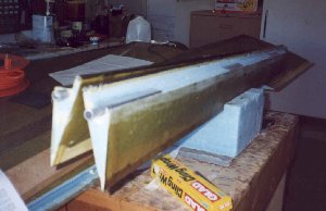
Next I attached the steel rods to the ailerons for counterbalance and inserted the hinge attach inserts after fitting the A10 tube in the inboard end of the aileron. After all this cured, I glassed over all this lapping 1 inch on the top and bottom surfaces of the ailerons with one layer of BID. Here are a couple of aileron pictures.
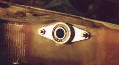
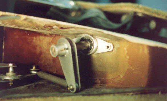
I ordered a pair of aileron control bearings from Infinity Aerospace and was very pleased with what I received. JD has been very helpful in offering building tips and has quite an offering of components for the canard aircraft builders. I encourage anyone to check out his WEB site. Anyway, I attached the bearings as JD calls out in his instructions. It took 2 days to complete the installation but only about 1 hour of total work. The rest was waiting for epoxy to cure. Here are a couple of JD's photo's showing the bearing and housing as installed.
I finished fabricating the rest of the aileron controls and installed them in each wing root and then turned each wing onto their leading edge to lay up the aft wing rib. This is a 2 ply BID layup with a third ply running across the hinge attach area. After this cured I attached the aileron hinges on each wing and fitted the ailerons. I temporarily bonded the hinges to the ailerons as outlined in the plans and then removed the aileron - hinges attached - from the wing. I then permanently attached the hinges to the ailerons with rivets. I re-connected the controls to make sure everything moved smoothly and was ready to move on to boring the wing attach holes.
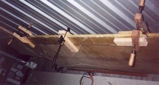
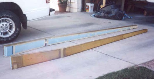
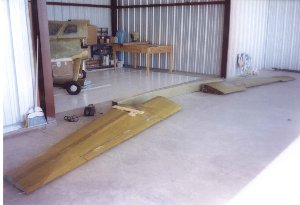
I took my center spar and laid out the dimensions called for to drill the pilot holes for the wing bolt bushings. After drilling them through with the 1/4 inch holes, I leveled the spar and lined up each wing along the floor of the hangar. I fitted the left wing to the spar being careful to line up everything level, then clamped it in place. Then I did the same with the right wing. I used a combination of a laser pointer, water level and carpenter's level to get it all right. After making minor adjustments for about an hour and deciding that everything lined up good and straight, I drilled the pilot holes through the wing hardpoints.
I then opened up each of the hardpoint holes to 5/8 inch using the spotface going nice and slow to keep the heat from building up. It took about 90 minutes to do both wings. I will mount the bushings in the holes after building the strakes. Here are the wings and spar laid out in my hangar prior to leveling everything.
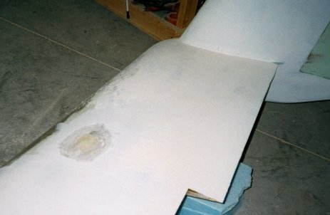
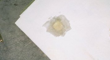
While contouring the wing surfaces, I noticed that the right wing had two defects that were a result of carelessness on my behalf. I had accidentally set a cup of epoxy on the wing, forgot about it, and it exothermed. The result was a bubble in the glass the size of the cup! I not only did this once, but twice! I had to remove the defect by sanding it away and feathering out the edges of the good glass surrounding it. Since the wing is three plies on the top surface, I feathered out three inches (one inch per ply is the documented method) and re-applied the plies in the correct orientation. A final ply of BID is then applied. After cure I sanded the area and filled it in and you'd never know it was there! Here are a couple of pictures of the affected areas after repair but before filler was re-applied.