Chapter 20
Winglets and Rudders
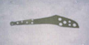
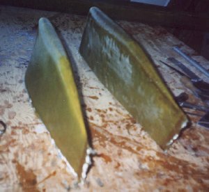
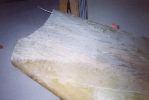
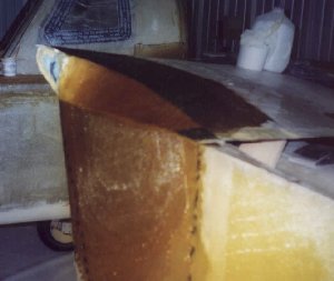
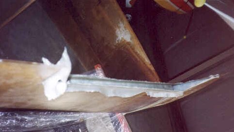
I jumped ahead a little bit prior to building the wings to make my winglets. I received the cores precut from AeroCad just like the main wings and prepared them for glassing. I first installed a COM antenna in each inboard side of the upper winglets and filled low spots with dry micro. I glassed each side per the plans except that I used an aluminum I-beam along the trailing edge to act as a straight edge similar to the main wings. Both the upper and lower winglets were glassed and I set them aside while I prepared the garage for the main wings. Here is a photo of the lower winglets prior to trimming.
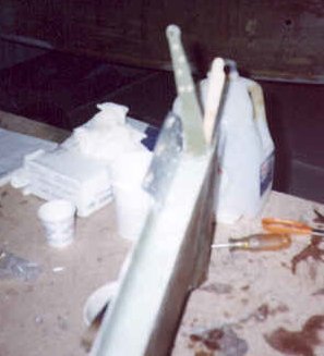
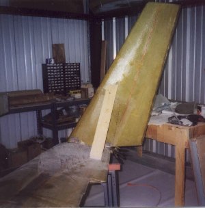
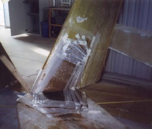
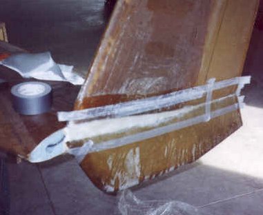
After getting moved into my new hangar, I set up each wing on saw horses and trimmed each winglet root and wing tip to the appropriate shape as explained in the plans. I was careful to make sure all measurements were accurate relative to the wing before making any cuts to the wingtips! I then temporarily attached the winglets to the wings with some thin sheet metal brackets and cleco's. I then bondo'd a board to the winglet and wing to get the proper angle of the winglet set and re-measured everything again. After ensuring it was OK, I bondo'd the winglet and wing together with a couple of blobs of bondo and let it set.
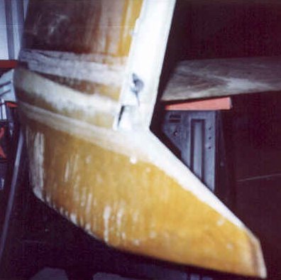
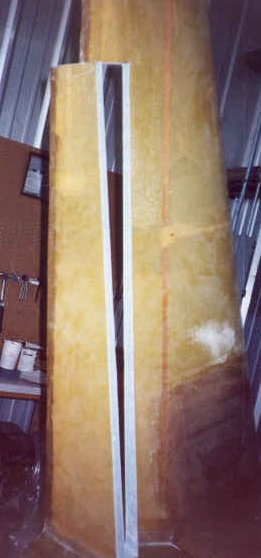
After the bondo was adequately cured, I flipped the right wing upside down and routed out the foam as called for in the plans in the wing tip / winglet root. I then laid up 8 plies of BID in this area, wedged some foam into the gaps and proceeded to lay up an additional 8 plies of BID across the bare foam. After this cured, I used pour foam to add foam to the junction area, let it cure and then shaved it down as shown in the plans. I then glassed over the foam with a combination of 2 plies of BID and 7 plies of UNI. The layup extended 15 inches onto the wing and winglet and tapered slightly smaller with each layer.
After cure, I flipped the wing back over, knocked out the support board and did the inside glass reinforcement which is the same schedule as the outside layup. After cure, I moved this wing/winglet out of the way and repeated the process with the left wing. I then attached the lower winglets to each wing with two plies of BID all around the joint and let it cure. The winglets are now fully attached and ready for the rudder fabrication.
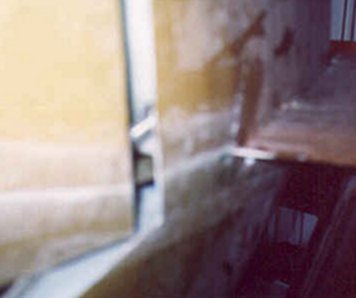
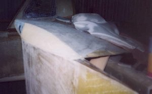
The rudders are cut out of the winglets in the same fashion as the ailerons are cut from the wings. The winglet then gets a 3 ply BID layup at the cutout along with two extra plys on the outer edge to give it more strength for hinge attachment. The hinges are drilled and attached to the winglet outer edge with just like the wing/aileron hinges. The rudder gets a similar BID layup at the cutout end and is then attached to the hinges using rivets.
I opted to install internal rudder bellhorns, so I also had to flox in this piece of hardware after the layup was done. The rudder cables get attached to this bellhorn internally and a spring forces the rudder to the closed position. The rudders only travel outward which is different that most airplanes. Upon landing, full deflection of the rudders initiates the brakes. Pretty neat!<