Chapter 22
Electrical
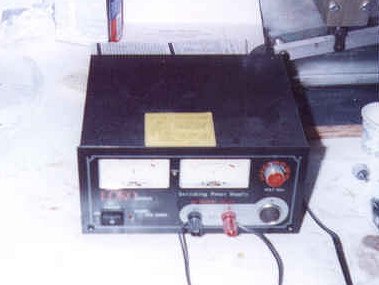
I started this chapter by purchasing some switches (split master, lights, radios, etc), a ground bus connector, three fuse blocks (6, 10 and 20 place) for the battery, essential and main power busses, Hobbs meter, wire and connectors. I intend on building up a basic IFR panel and ordered a number of radio and avionics brochures in order to plan space and electrical needs. I also purchased a 28-amp bench-top power supply that I will use to debug my circuits as well as allow me to actuate electrical components when needed (such as raising or lowering the nose gear, speed brake, trim system, etc). It sure beats running cables from my automobiles! Here is a photo.
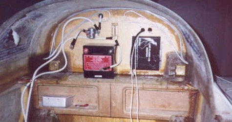
I mounted the essential and main power busses length-wise on the fuselage wall just forward of the instrument panel on the co-pilot's side. The #2 wire coming from the battery contactor ties into the main bus and the essential bus is tied to the main. thru a diode. The battery bus is located nearby.
In December of 1999, after completing the firewall chapter and having the engine ready to mount, I decided it was time to start running the wires. I laid out my system requirements and relied on the book "The Aeroelectric Connection" by Robert Nuckolls heavily. I purchased a 25AH RG battery from B&C Specialty Co. and will mount it on top of the spar.
The heavy wires were run first. #2 wire is run from the battery positive to the input side of the battery contactor. #2 is also run from the output side of the battery contactor to the main power bus. An additional #2 wire is run from the output of the battery contactor through the firewall to the input side of the starter contactor. Finally, one more #2 wire goes from the output of the starter contactor to the starter.
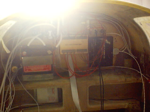
This next picture (sorry for the glare) shows the final battery location, the VM1000 engine monitor CPU (center), electronic ignition (right) all wired up. Wires still need to be bundled. This whole area will be enclosed by a panel to cover it up.
The ground bus is also #2 wire and starts at the battery negative to a 24 position fast-on tab ground bus mounted on the cabin side of the firewall. Attached to the same point on the firewall ground bus is another long #2 wire that runs to a 48 position fast-on tab ground bus mounted on the lower right front side of the instrument panel. All ground connections will terminate at either of the two ground busses.
The aircraft is equipped with two alternators, a 60 amp B&C is the primary alternator and a smaller 20 amp backup alternator that is located at the accessory pad (normally where the vacuum pump is mounted). The 60 amp unit will supply all the power for my all-electric panel and the backup unit will be used to power the essential bus should my primary alternator fail. Each alternator has its own regulator with over-voltage protection that are mounted on the fuselage wall on the pilot's side forward of the instrument panel. Power from the 60 amp alternator comes through a #4 wire to the firewall where it goes through a large fuse before connecting to the input side of the starter contactor. This essentially connects it to the power bus.
Each large cable had to be cut to length and have terminals soldered to the ends. I had to use a butane torch to heat the cables up in order to get the solder to flow, but the torch made short work of it. Each terminal had heat shrink tubing applied to make an attractive and safe end.
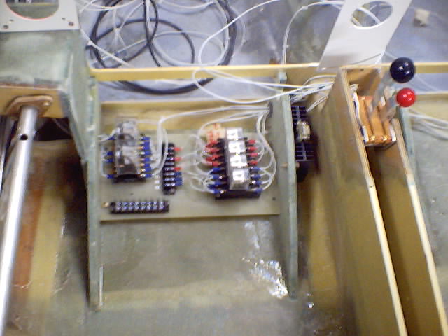
Pitch Trim, Speed Brake, and Landing Gear Relays
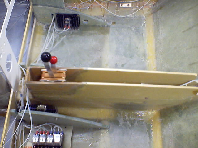
April 2001) The actuator motors for pitch trim, speed brake and nose gear are all controlled through relays mounted underneath the pilot seat. The relays are wired to make the motors change direction or stop when a limit switch is triggered. The landing gear switch is on the panel in the column between the pilot and co-pilot. Besides the relays, there are LED indicators to tell the status of the gear as it is moving - green for UP, red for DOWN, yellow for IN TRANSIT. The pitch trim and speed brake switches are mounted on the pilots stick grip along with the radio push-to-talk. I have a couple of other switches mounted on the stick grip, but they are unused at this time. All other switches are on the panel.
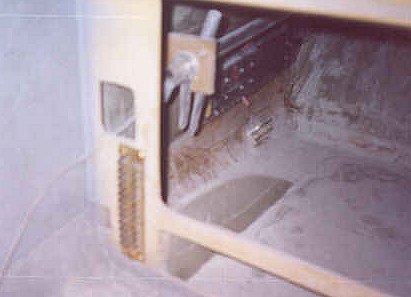
The lighting dimmer control is mounted on the pilot's right side seat support. It has a 9-pin D-sub connector to give plenty of connections for all instruments with dimming capability. There is also a heat sink mounted to the co-pilot's right side seat support that sinks heat away from a diode used to control current through the main and essential busses. Should I ever need to switch off the main bus, I can still power the essential bus through the alternate feed from the battery bus.
Wire Bundles
(April 2001) I am amazed at the number of wires it takes to power up the goodies in this aircraft! If you consider that I have a dual alternator system with 3 independent busses (main, essential and battery) and every device hooked up to these busses has at least a power and a ground wire, it does add up. Anyway, I have been going through the process of pairing up all the wiring and bundling them with tie wraps about every 4 inches. All the wires are now bundled in this way, including the avionics wires that run only behind the panel. After tie wrapping all the wires, I've taken these bundles and grouped them in bunches and mounted them along the sides of the fuselage with Adel clamps screwed into the fuselage walls. The areas in the fuselage walls are reinforced with 3-4 layers of BID so that the screw has something substantial to hold.
Avionics
My avionics selection has me really excited! I decided I wanted a new, state-of-the-art panel as long as I didn't go broke in the process. I purchased all my avionics through Southeast Aerospace. Here are the details of what the panel is fitted with:
To start, I wanted a nice audio panel with marker beacon and stereo intercom. I chose the Garmin GMA340.
Next was the navigation and communication radios. Since the panel height is limited, I liked the Apollo Slim Line instruments by Garmin AT (previously UPS Aviation Technologies)). These radios are full featured and are only 1.3" tall. I selected a SL30 Nav/Comm for traditional VOR navigation and a CNX80 which combines a GPS/WAAS navigator, a Nav/Comm with VOR Nav, localizer, and glide slope receivers all in one compact package. The transponder is a fully digital SL70. I'll also have a MD-200 CDI from Garmin AT that is switchable from either NAV or GPS thru the CNX80.
Well, I HAD to go one step further and get a multi-function display capable of displaying a moving map, flight plan, terrain and weather. I chose the Apollo MX-20. The MX20 is currently equipped with the Chartview option which allows it to show approach charts and airport diagrams just like the Jeppeson paper version.
My engine instruments will be displayed on a Vision Microsystems VM1000 and I have the EC100 fight warning system as well. The VM1000, associated transducers and the EC100 are beautifully small units with lots of functionality. All of the transducers are installed and ready for engine on! Check out Chapter 23 for details on the installation of this system.
My flight instruments include:
Electric RC Allen Attitude Gyro (way long lead time - 6 weeks)
Electric RC Allen Direction Indicator (way long lead time - 6 weeks)
Airspeed indicator
Altimeter
Single axis autopilot by Trio Avionics
Lastly, a Rocky Mountain Instruments MicroEncoder will act as an altitude encoder but will also display vertical speed as well as other functions (altitude, OAT, TAS, timer, etc). This one can be purchased as a kit, so I said, "why not?" and purchased it that way. OK, so I work for Intel and think I know a little bit about soldering and electronics, but when I saw the kit arrive - wow - did I ever think I made the wrong choice. I dug in and spent about 4 weeks overall (no more than 20 hours total) assembling this thing and actually made it work first time! I impressed myself, although if you follow the directions, it can't help but work. The instructions are very easy and the parts are laid out perfectly to make it all go very smooth.
One final whole location is left on the panel for an instrument to be determined later!
Well, of course I also have some switches and indicator lights and stuff like that.
As far as an entertainment system goes, I will install a radio/CD player just under the radio stack. A remote jack in the rear cabin area will accept input from a portable music device. The audio panel accommodates two independent music sources, so this works out great for the adults up front and the kids in the rear.
After going thru the process of building a custom aluminum panel to replace the fiberglass panel bulkhead in the plane, flying 45 hours with it and then making so many changes that it became unusable, I fabricated a custom fiberglass/carbon panel with canted radio stack and engine display bays. I fabricated the new panel by making a base of 2 inch thick foam with the canted features for tilting the radio stack and engine display more toward the pilot. I then laid 8 layers of BID and three more layers of carbon cloth to help stiffen it. After it cured, I trimmed the panel to size and cut the holes for all the instruments, radios, switches, etc. I then glassed the panel in the plane and started re-installing the equipment. One other change I made in this process was to re-do the avionics wiring using t a new hub and cable system by Approach Systems. This made wiring the new panel much faster and allows for making changes easier. I'll add a much newer photograph once I get a chance.
At the end of August, 2001, the panel was wired and fully operational with the first custom aluminum panel. All avionics checked out and are functioning: the GPS acquires satellites, the MicroEncoder sends altitude info and all this stuff is displayed beautifully on the MX-20! What a thrill it was to make my first radio call from N309BD to Chandler Ground Control for a radio check (it came back loud and clear, thank you very much!). Well, another chapter completed!
2004 - A completely new panel and rewire!
Around November of 2003 I had the opportunity to get a good deal on a new GPS radio. In fact, it was the new CNX80 by UPSAT. Well, without too much thought I purchased the radio and then started to think about how I was going to install it in the existing panel. It turns out there was no way I was going to get that new radio in the panel without some massive cutting and patching. Well, to make a long story short, I decided to build a new panel and rearrange the radio stack to not only include the CNX80 but also add a AM/FM CD player as well. My first panel was a metal panel fabricated to allow for easy removal in case I ever needed to do maintenance. Turns out I never really found a reason to do that after all. Another problem I had with the metal panel was that I ended up installing it 2 inches further aft than originally designed due to a miscalculation on my part when installing one of the avionics. It interfered with the canopy and the only way to fix it without a new panel at the time was to move the panel. I never did like that decision, but it was the only choice at the time. Well, now I knew I had to fabricate a new panel anyway and I decided I was going to do it right this time!
I knew after flying the plane with the old panel that engine instrument display (VM1000) at the far right side of the panel was a little difficult to see without moving my head over that direction. I wanted to tilt the display toward the pilot on the new panel. At the same time I decided to tilt the radio stack as well to make them easier to see. So, my plan was to make a tilted panel instead of a flat panel. I started by forming a foam plug to use as a base for the panel. I would get the shape I wanted from the foam, cover is with a release agent and lay fiberglass over it. After the glass cured, I would removed the foam and be left with a solid glass panel. The process took about 3 days. I laid up 8 layers of BID glass over the foam and after removing the foam decided it wasn't quite stiff enough so I added two layers of carbon fiber cloth to the backside to stiffen it. This worked out great and the result was just what I was looking for. I trimmed and sanded the panel and started to lay out the instrument holes, radio stacks and various holes for switches, lights and such. After everything was laid out just right I started cutting.
I then knew it was time to pull the old panel from the plane and permanently glass in the new panel. Once I started to pull out the radios and instruments, I realized I really wanted to redo some of the wiring. I mean REALLY redo it! I knew my new panel would be heavier due to the addition of more radios and I new it would be two inches forward from the old location. This was going to have a positive effect on my CG (moving it forward). I had relocated the battery from the spar to the nose about 10 hours in to my test flights due to CG issues. I never liked having the battery that far from the starter though and I was looking for a good reason to move it back to the spar. So, I decided I would take this opportunity to do that. Oh, and since I was moving the battery, how about moving the fuse blocks from under the armrest to just forward of the instrument panel. And how about relocating the relays for the pitch trim, nose gear and speed brake while I'm at it. It'll clear up the area under the pilot's seat and make it available for storage again. Hmmm, shouldn't take too long to make those changes, right?
After removing the old panel, I taped the new panel in place, did some final sanding and prep work on it and brushed on a couple of coats of K36 primer. After sanding this smooth, I masked off the whole plane except for the panel and shot on a few coats of my silver metallic trim paint. The panel looked great if I do say so myself! I then began the process of re-installing all the instruments, switches, radios, etc. Here are a few pics of the panel about half way through the re-installation.

Wires hanging out of the new panel.

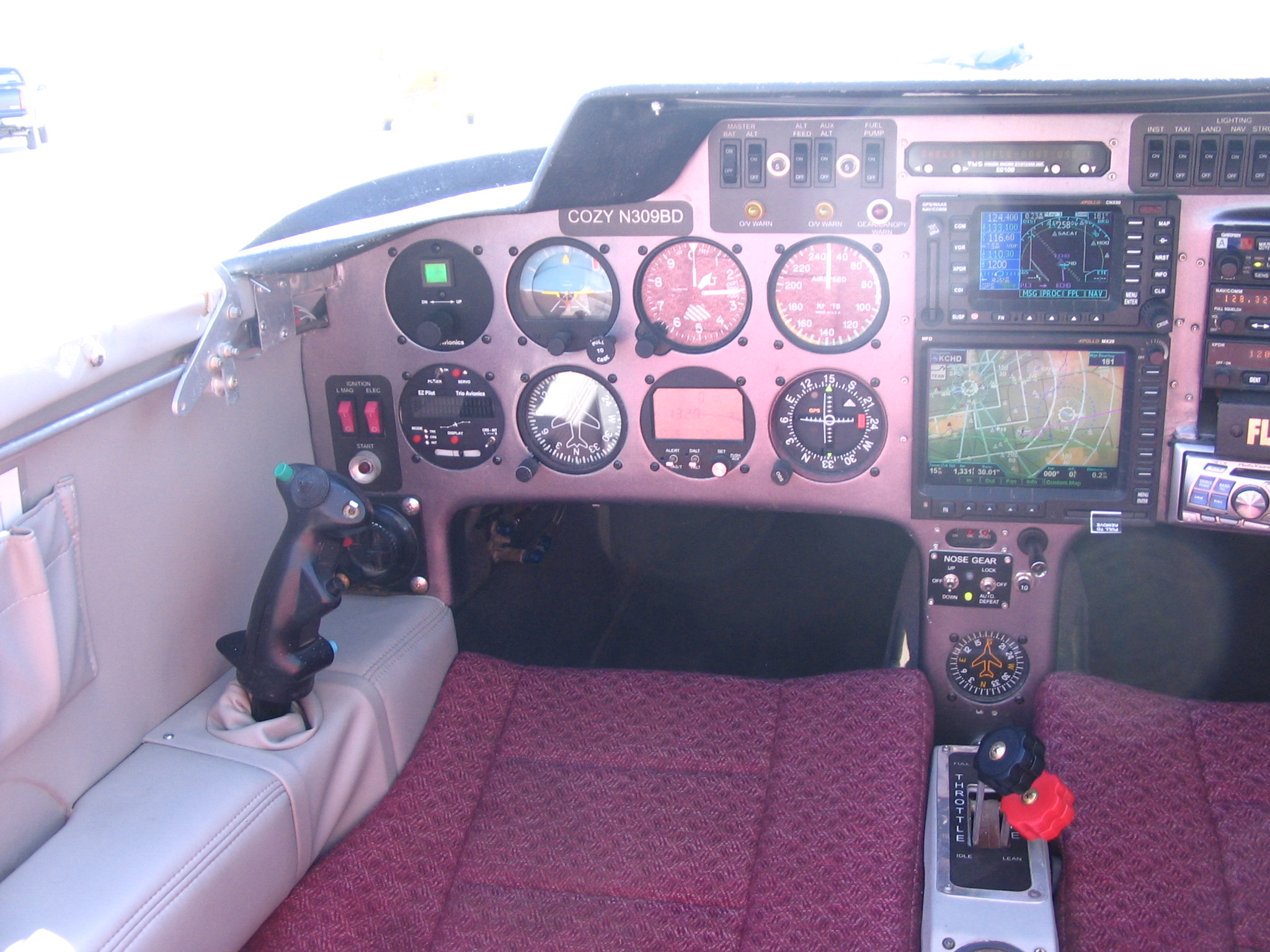
Pilots side instrument cluster.

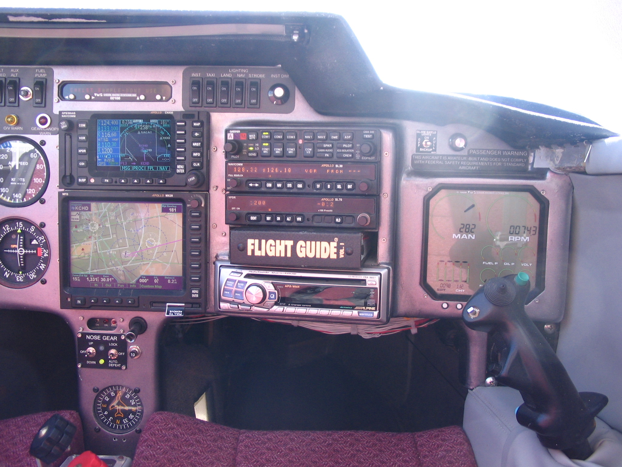
Right side radio and engine instrument display bays.

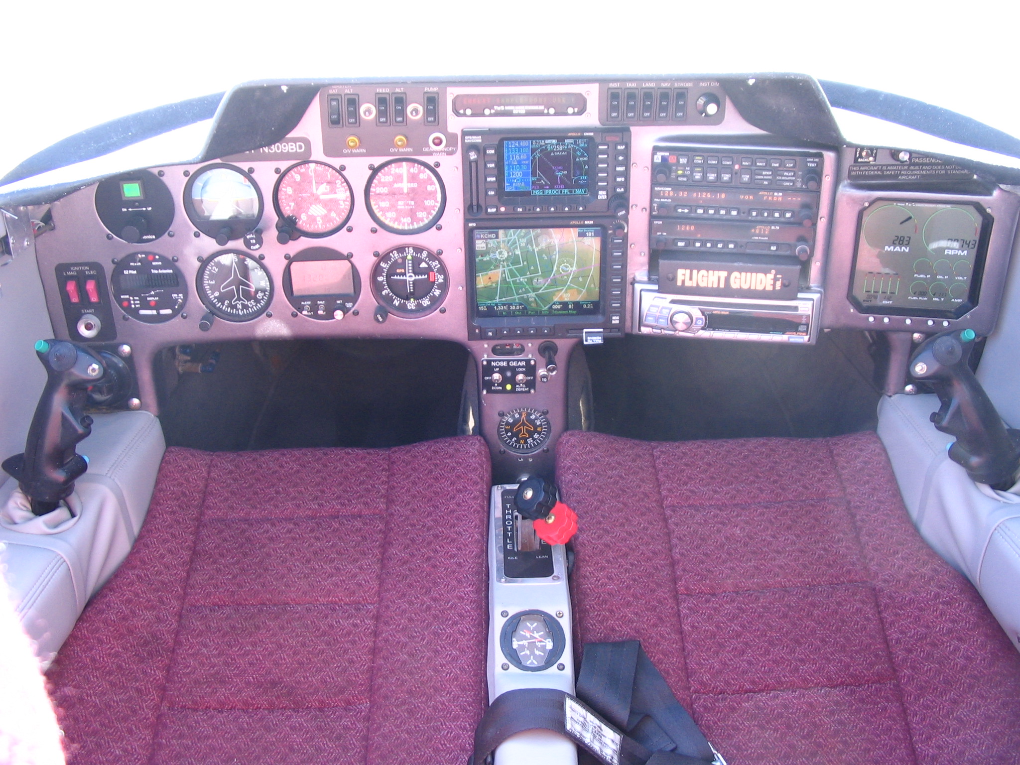
Full panel.
Well, after 6 weeks of rewiring, moving fuse blocks, relays and the battery, I had everything back together and ready to check out. I must say the new panel is everything I had hoped it would be. What do you think? The pictures below were taken Oct '05 after installation of a new altitude hold (upper left) and landing gear switch panel (center console below MX20 MFD).