Chapter 24
Covers and Fairings
This chapter includes details for installing the armrests, seats, canard cover and miscellaneous other details that have waited until near the end of the construction for one reason or another. I have jumped to this chapter on and off throughout the project when it was OK to do so.
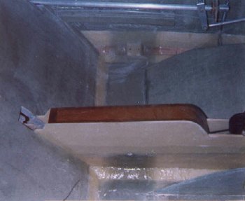
Armrests
Armrests are constructed in both the front and rear of the fuselage and cover the control tubes for the ailerons, electrical conduits, and in my plane the fuse holder as well. I will build in audio control jacks into the armrests as well as I finish off the electrical section. The armrests are constructed of 3/8 inch foam covered with BID and fitted over the control tubes. The fronts have map pockets built into them as well. The front center armrest cover is hinged to allow access to precious "cargo" space. Here are some preliminary pictures.
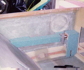
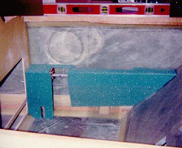
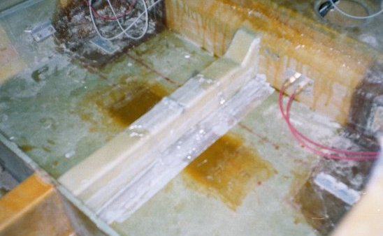
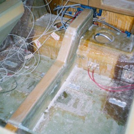
Seats
The seats are constructed of the same 3/8 inch foam as the outer fuselage skin. For the front thigh supports, ribs are installed first and the seat portion is formed over the ribs to get the required shape. The rear seats are similarly constructed. I had originally decided to build a bench seat, but chose recently to follow the plans and build a center console and separate seats. Here is a picture of the rear seat console.
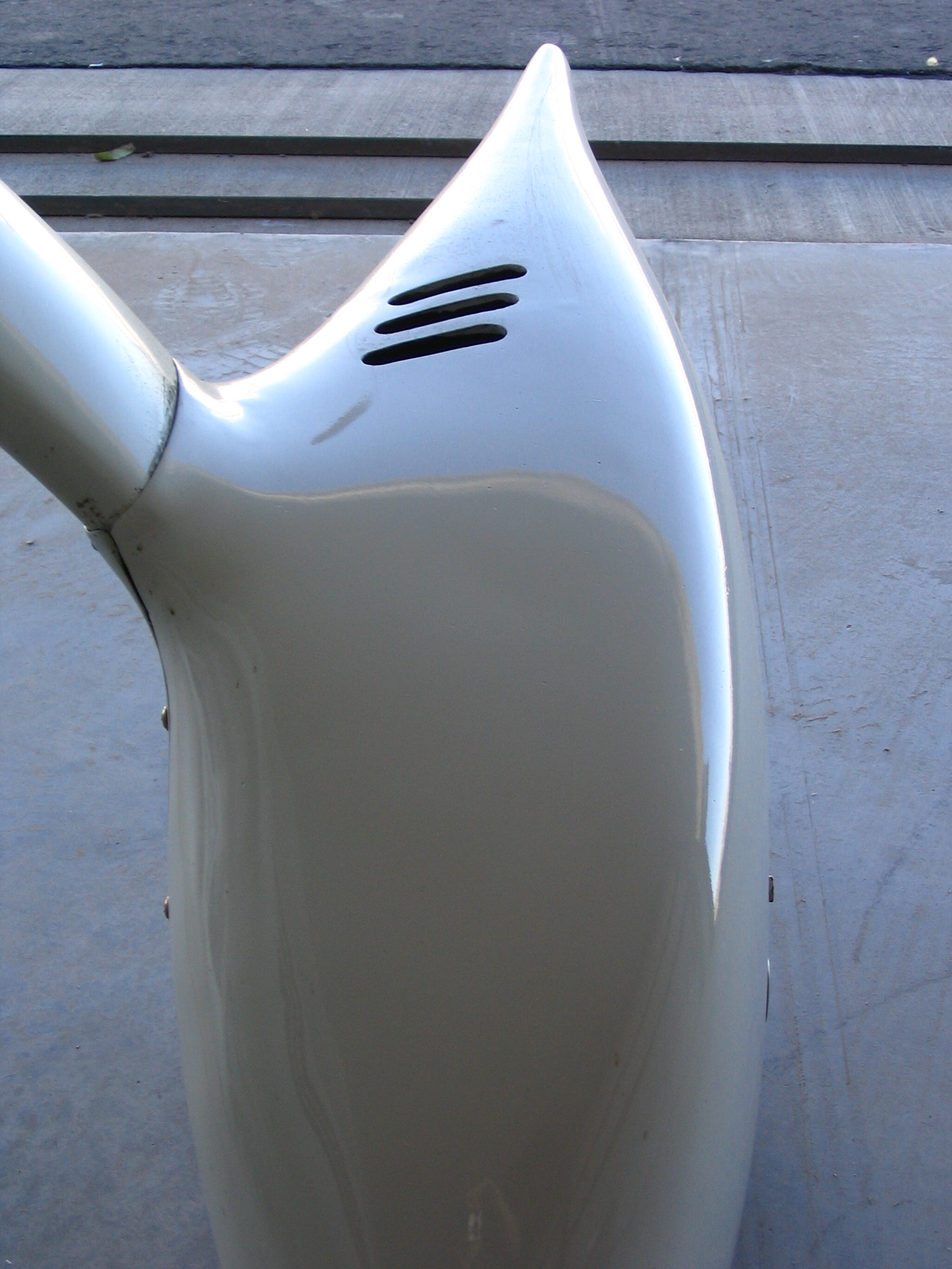
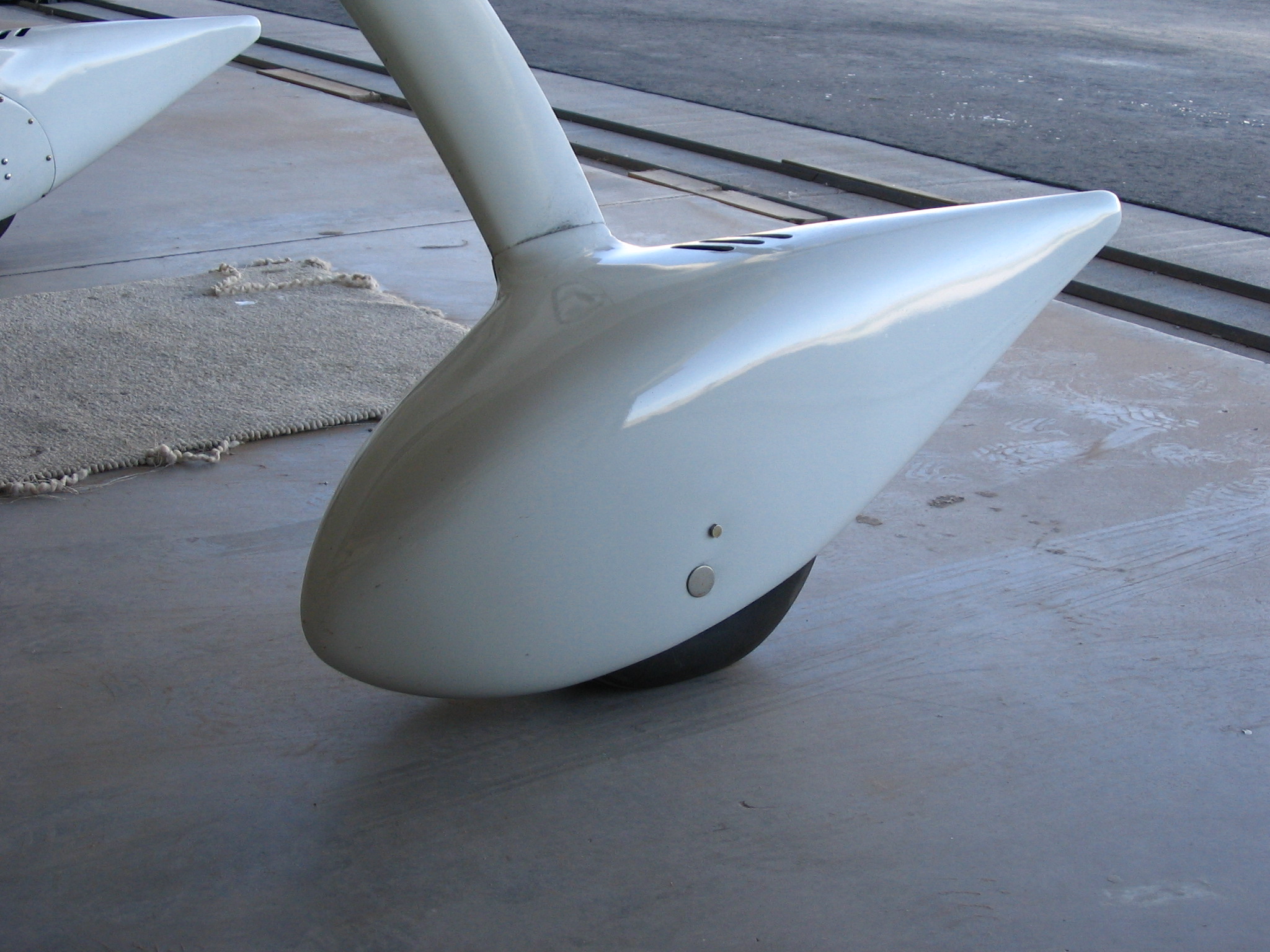
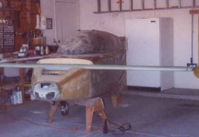
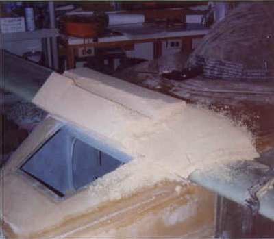
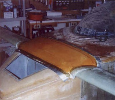
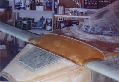
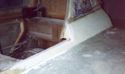
Canard Cover
The canard cover blends the canard into the fuselage in the nose area. The canard is attached to the fuselage and block of foam are micro'd to the canard and carved to contour this area to match the fuselage. After the foam is carved, two layers of BID are used to cover the foam. The canard is removed after cure and the bottom of this piece is glassed to close off any exposed foam. Lips are added to shed rain and cover the joints. Here are a series of photos showing the process.
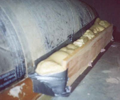
Strake fairing
The fairings are built to offer a smooth transition from the fuselage to the engine cylinder bulges in the cowling. You start by applying pour foam into a makeshift dam and then carving the foam to shape, laying on glass and cutting free the canopy since part of it is attached to the fairing. Here are a couple of pictures.
Main Wing Vortilons
For some reason I cannot locate where the plans talk about these, but they are shown on a full size template drawing and give enough detail so that they can be built. The vortilons are small, thin wing shaped protrusions that are placed along the leading edge of each main wing. There are three per wing and are made by laying up a couple of plies of BID, butting them to shape and then masking off the area of the wing where they attach with plastic wrap. The vortilon lays at a 67 degree angle to the leading edge (this is so they stick straight into the wind - remember the main wings are swept backward by 23 degrees). You lay up an additional 2 plies of BID on each side of the vortilon and lap it up onto the wing surface. After cure, the vortilon gets popped off the plastic wrap, trimmed and painted. They are attached to the wing with RTV after the wing is painted.
Landing gear leg fairings / wheel pants
The gear leg fairings were made by making a cardboard template and taping it to the gear leg and fuselage and using modeling clay to get a pleasing shape. I then laid up 2 plies of BID over the top and bottom of the leg. After cure, I cut around the perimeter of the fairing in a straight line so that the landing gear cover could be removed along with part of the fairing. The cut also allows the gear to flex in landing.
I purchased a set of pre-molded wheel pants from Featherlite and installed them after the plane had flown for 50 hours. The parts were the worst molded parts I have used in this project and required quite a bit of work to get into reasonably presentable shape. After what seemed like 100 hours of sanding, trimming, shaping, etc. I finally decided to settle with what I had and leave it alone (for now). Here are a few pictures of the completed wheel pants.